Integration of miniaturisation technologies
Posted: 20 May 2005 | | No comments yet
In pharmaceutical drug discovery research, several technological advances have moved in vitro biological and biochemical experiments from the laboratory benchtop to fully automated high-throughput screening (HTS) robotic platforms1,2.
In pharmaceutical drug discovery research, several technological advances have moved in vitro biological and biochemical experiments from the laboratory benchtop to fully automated high-throughput screening (HTS) robotic platforms1,2.
In pharmaceutical drug discovery research, several technological advances have moved in vitro biological and biochemical experiments from the laboratory benchtop to fully automated high-throughput screening (HTS) robotic platforms1,2.
Approximately two decades ago, HTS was instituted in pharmaceutical company laboratories in order to assay large numbers of medicinal chemistry compounds for biological or biochemical activity. In its infancy HTS borrowed heavily from the clinical chemistry industry, employing automation and detection technologies similar to those that had been used to assay the constituents of a patient’s biological sample.
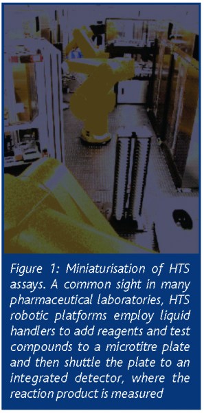
HTS laboratories have evolved significantly since then. In order to screen a compound library against the various therapeutic targets in a pharmaceutical company’s research portfolio, HTS technology has become more specialised, robust and automated. Most HTS laboratories have at least one robotic platform, consisting minimally of an anthropomorphic robotic arm (or plate track), various liquid handlers, detectors and incubators, all under control of centralised scheduling software (Figure 1).
Recently, HTS laboratories have been faced with new challenges. In addition to the increasing size of research portfolios, pharmaceutical company compound libraries have also grown. In an effort to contain HTS assay costs and minimise test compound consumption, pharmaceutical companies have proactively sought technologies that permit HTS assays to be performed in miniscule volumes, i.e. less than 10 μL/well. During the past five years, there have been significant successes in this effort – most notably in the microtitre plate, liquid dispensing and detection technology domains. This article will present the recent advances in each of these three technology domains.
Microtitre plate technologies
A variety of microtitre plate formats are available to the HTS researcher. The 384 well microtitre plate, which has been adopted widely by HTS laboratories during the past five years, is perhaps the most popular format. Although the 384-well microtiter plate is an economical alternative to its predecessor, the 96-well microtitre plate, it is not the endpoint for HTS assay miniaturisation.
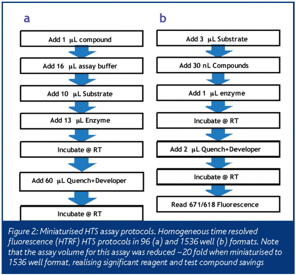
Generally, an assay is considered miniaturised if it can be performed in a format denser than 384-wells. Significant economic advantages are realised if an assay can be miniaturised to the 5 microlitre assay volume of the 1536-well microtitre plate (Table 1 and Figure 2). Although an assay may be further miniaturised to the 2080 or 3456 well formats, the 1536 well format remains a popular goal for most HTS miniaturisation efforts. This is most likely due to the availability of 1536 well plates in the same variety of colours and materials as the 96 & 384 well formats. In addition, since the 1536 well microtitre plate conforms to an accepted standard3, several HTS vendors have built liquid handlers and detectors that are compatible with this format.
Regardless of the miniaturised format, evaporation is an important issue with microtitre plates denser than 384 wells. This is especially true if the protocol requires an extended incubation time or has less than a 5 μL assay volume. Fortunately, this can be addressed with proper laboratory humidity and temperature control. In addition, several microtiter plate vendors have developed novel lid-to-plate sealing technologies that are effective in combating evaporation.
Liquid handling technologies
Automated liquid handlers are pervasive in the HTS laboratory. In a typical robotic HTS assay, microtitre plates are shuttled between different automated liquid handlers responsible for dispensing assay reagents and, if necessary, transferring compounds from a compound storage plate to the assay plate. For heterogeneous HTS assays, additional steps may be required to transfer reaction products from one assay plate to another or to wash non-plate bound constituents from the assay plate. Regardless of the protocol steps, the most common techniques used in HTS liquid handling fall into one of three categories: non-contact dispensing, liquid transfer and plate washing.
Non-contact dispensing
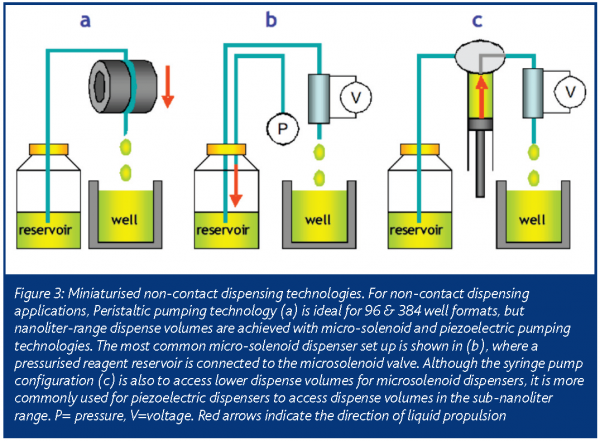
A variety of technologies are commercially available for miniaturising non-contact dispensing (Table 2). Historically, peristaltic pumps have been used for this application in 96 and 384 well format HTS assays (Figure 3). Currently, the most popular equipment used for miniaturising dispense volumes employ some variant of micro-solenoid technology. Originally developed for the printing industry, it has been incorporated into several HTS-compatible liquid handlers4.
For HTS dispensing applications, a micro-solenoid is used as a liquid valve. To enable liquid dispensing, a pressurised fluid is connected to its inlet and a sub-millimeter internal diameter nozzle is connected to its outlet. Through rapid, microprocessor-controlled actuation of the micro-solenoid, discrete quantities of the fluid are ejected from its outlet. By precise control of the time the valve is open and the backpressure of the reservoir fluid, dispense volumes in the sub-microliter range can be achieved. With the addition of a syringe pump, even smaller dispense volumes are possible. In this configuration, the micro-solenoid valve can also be used to aspirate fluids through its nozzle.
If further miniaturisation of non-contact dispensing volumes is required, piezoelectric transducers can be employed5. Commonly used in a variety of electronics applications, the defining characteristic of a piezoelectric transducer is its ability to change shape upon application of a voltage. When a piezoelectric membrane forms one wall of a narrow dimension fluid channel that has a sub-millimeter internal diameter outlet nozzle, the entire assembly can operate as a micro-pump. Dispensing is achieved by rapidly pulsing a voltage across the membrane, causing it to flex and displace a volume of liquid from the assembly. In this configuration, a piezoelectric micro-pump dispenses volumes reliably down to the picoliter range. With syringe-pump modifications similar to those discussed above for microsolenoid valves, the piezoelectric pumps can also aspirate small volumes of precious fluid.
Regardless of the technology, implementing sub-microliter dispensing technologies in an HTS laboratory can be challenging. Prevention of clogging is the greatest challenge. This is because the fluid paths of miniaturised dispensing technologies have necessarily small fluid channel dimensions that can trap particulate or air bubbles. The solutions to most of these problems involve reagent filtration and/or de-gassing. However, such solutions may not be applicable if the particulate is a necessary part of the reagent (e.g. mammalian cell suspension, SPA beads). A less frequent but equally cumbersome challenge for miniaturised volume dispensing is static electricity. If it is present on the dispenser tip, microtitre plate or in the path of the ejected droplet, ionisation has a sufficient force to deflect ejected droplet(s) from their intended trajectory. This effect can be minimised with establishment of environmental controls and deionisation technologies to prevent build up of charged ions in an HTS laboratory.
Liquid transfer
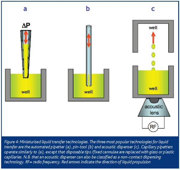
Typical HTS protocols requiring liquid transfer technologies are (a) transferring an aliquot of test compound from a source plate to a compound or assay plate and (b) the transfer of a biochemical or biological supernatant from one assay plate to another. Although the bulk dispensing technologies described above could be used for liquid transfer, more robust technologies have been developed (Table 2). For at least two decades, the most popular technology for liquid transfer remains the automated pipetter, but a variety of newer technologies are now available (Figure 4).
Similar to the handheld laboratory pipette, automated pipetters rely on air displacement to aspirate and dispense fluid from a bank of disposable tips or fixed cannulae. In most examples, accurate and precise microliter-range pipetting is achieved by attaching the pipetting piston mandrel to a computer-controlled stepper motor. Depending on the needs of the HTS protocol, the tips/cannulae can be exchanged and/or washed with cleaning solvents after each transfer. Although automated pipetters allow flexible and reliable transfers in the microliter range, they have limited applicability in sub-microliter volume ranges. This is due largely to the liquid surface tension effects that dominate in this volume range, negating the precision of the pipetter stepper motor.
When an HTS protocol requires a sub-microliter volume transfer, pin-tools6 or capillary pipetters can be used. Both technologies exploit surface tension effects to control the volume of liquid transferred and permit transfer volumes in the nanoliter range. A typical pin-tool consists of a bank of sub-millimeter diameter pins, with or without slots etched into the tip of each pin. The pin-tool can be mounted to an automated pipetter head, replacing the disposable tip or fixed cannulae assembly. To transfer liquid, the pin-tool is first immersed in the liquid to be transferred. Once immersed, a small volume of the liquid coats the surface and/or slot of each pin. To release the liquid, the pintool is dipped into the destination microtitre plate. Once in the source wells, diffusion (for a wet transfer) or surface tension of the plate bottom (for a dry transfer) forces the liquid to leave the pins.
A capillary pipetter is a further refinement of the pin-tool technique. It consists of a bank of sub-millimeter inner-diameter capillaries, similar to those used in capillary electrophoresis analytical techniques. To perform a transfer, a capillary is first dipped into the liquid to be transferred. Once a capillary is submerged in the liquid, capillary action forces small volumes of the liquid to collect in its inner annulus. Air displacement techniques can also be used to increase the volume of liquid aspirated and/or assist in dispensing the contents of the capillary.
An incumbent limitation to pin-tool and capillary-based techniques is their limited range of transfer volumes. Although the volume transferred by a pin can be controlled by a variety of factors (including dip speed, plunge depth of the pin-tool, column heights of the source and destination well fluids), the most straightforward method is to change the pin diameter or its slot size. While a capillary based transfer method offers a little more flexibility in the choice of volume transferred, both techniques suffer from the difficulty of mechanically mixing the transferred liquid with its solvent. However, these shortcomings are compensated by the robustness of these technologies. Especially in the case of the pintool, the lack of moving parts guarantees less frequent service and maintenance when compared to other miniaturised liquid handling technologies.
Acoustic energy-based liquid transfer technology represents the most recent advance in miniaturised HTS liquid handling7. The technology consists of an acoustic lens and piezoelectric assembly that transduces a radio frequency (RF) input into a high frequency sound beam. To transfer liquid from a microtitre plate, the assembly is coupled to the plate bottom and the acoustic beam is focused onto the meniscus of the liquid. Energy imparted by the beam causes discrete droplets to be ejected from the surface of the liquid. A destination microtitre plate is strategically placed to capture the droplets. In general, the size (ergo volume) of an acoustically ejected droplet is inversely proportional to the input RF. Acoustic dispensers are currently tuned to dispense volumes in the nanoliter range for liquid transfer applications, but they are capable of dispensing picoliters of fluid.
Acoustic dispensers are perhaps the most sophisticated liquid transfer technology. A successful liquid transfer depends on a variety of parameters including the shape of the acoustic lens, the dimensions of the fluid reservoir, the physical properties of the reservoir fluid and the materials used to construct the reservoir vessel. In addition, an acoustic dispenser employs sophisticated electronics and hardware similar to those used in sonar.
A distinguishing characteristic of acoustic dispensing technology is that a reagent can be dispensed without any contact between it and the acoustic dispensing apparatus. This gives acoustic dispensing technology an important niche in the HTS laboratory. Often acids, bases, solvents or otherwise incompatible liquids cannot be dispensed by traditional ‘flow-through’ HTS dispensing technologies. Although not currently implemented, it is easy to envisage acoustic non-contact bulk dispensers in the near future.
Plate washers
Plate washers for higher density formats do not differ significantly in principle from their 96 & 384 well counterparts. Even in 96 and 384 well formats, plate washing is cumbersome to automate. Although an automated pipetter can perform a wash protocol, a microtitre plate washer employs at least two multi-tip manifolds to decrease the aspiration and dispense times. Typically, vacuum is applied across one manifold in order to aspirate liquid from the plate and pressure is applied across the other manifold in order to refill the plate with liquid. Regardless of format, all plate washers suffer from the same problems in HTS campaigns. The manifolds can easily clog and require significant maintenance to insure that vacuum and pressure is evenly distributed across the manifold. Regardless of these problems, the pharmaceutical industry need to miniaturise heterogeneous HTS assays still spurs innovation in this technology domain.
Detection technologies
Since most HTS campaigns employ fluorescence or luminescence assays, sensitive detection technologies are necessary for accurate measurement of compound activity. Traditionally, photomultiplier tube (PMT) based detection technologies have been used to collect and quantify the small amounts of photons produced by these assay formats. For assay formats that have high photon fluxes (e.g. absorbance measurements), less-sensitive photodiodes (PD) are used.
Although both PMT and PD technologies remain popular in HTS laboratories, they have intrinsic limitations. Since by design they have limited spatial resolution, the detectors measure assay photon flux by scanning each well of a microtitre plate in a serial fashion. Due to the serpentine motion of the detector assembly as it performs this task, these detectors have been nicknamed ‘plate readers’. For assays that require long per-well measurement times (e.g. radiometric detection methods), the plate-reading process becomes time consuming and often the rate limiting step in automated HTS campaigns. Although plate readers with banks of PMT/PD detectors have been constructed to address this issue, calibration and maintenance of several detectors is cumbersome in an HTS setting.
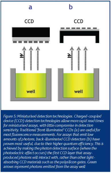
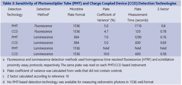
During the past five years, charged-coupled device (CCD) detection technology, commonly used in video cameras, has become increasingly popular for HTS assay miniaturisation efforts. The first successful application of CCD-based technology to HTS was driven by the need to measure intracellular calcium and membrane potential transients8. For this application, a cleverly designed instrument used a CCD detector to measure the response of every well simultaneously by imaging the entire plate over a given time interval. More recently, advances in CCD sensitivity & design (most notably with the introduction of back-illuminated CCD cameras) have allowed HTS researchers to measure low photon producing luminescence assays (FIGURE 5)9. Additionally, CCD detectors can perform absorbance-based measurements, obviating the need for an instrument with both PD & PMT functionality. In most cases, the amount of time required for a CCD-based detector to image a 1536-well plate is dramatically reduced from its PMT or PD counterpart, with little loss in assay data quality (Table 3).
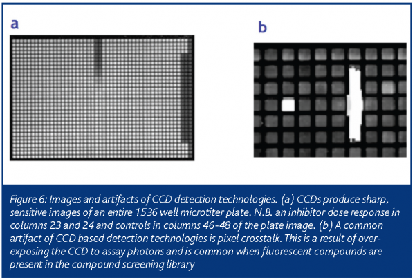
An important artifact that is incumbent to CCD-based detection methods is the presence of pixel-to-pixel crosstalk. If too many photons impinge upon the photoelectric sensing surface of the CCD, electrons ‘leak’ from the affected pixels to neighbouring pixels as the CCD shift register and amplifier converts the electronic signal into digitised information. This results in images with bright streaks in a horizontal or vertical fashion, depending upon the orientation of the shift register to the CCD (FIGURE 6). Additionally, CCD detection technologies are sensitive to liquid viscosity, especially in trans-absorbance based measurements. With high viscosity reagents, surface tension causes the formation of a large meniscus within a well. The meniscus then acts as a lens to scatter light away from the CCD collection optics and hinder reliable measurement of well-to-well light intensity. Regardless of these issues, an assay that can be adapted to a CCD-based detection method will benefit from dramatically reduced plate read times, removing the bottleneck long associated with plate read times in 1536-well miniaturised assays.
The future of HTS miniaturisation
Through integration of the miniaturisation technologies such as those described above, several (HTS) laboratories have evolved from labour-intensive, batch-based, semi-automated operations to fully-automated assay ‘production lines’ with low consumable and reagent costs. Additionally, miniaturisation technologies continue to migrate from HTS labs to drug discovery operations upstream & downstream of HTS efforts. This has had the desired effect of relieving bottlenecks associated with target validation and compound lead identification.
The need remains for further innovation in HTS technology miniaturisation. For example, refinements in technologies such as plate washing, automated liquid dispensing calibration, microfluidics or novel calorimetry and image-based detection technologies will gain more popularity as they allow laboratories to run different types of assay protocols with increased efficiency and lower reagent costs.
Perhaps the greatest frontier in future HTS miniaturisation efforts will be multiplexing several assays within a single microtitre plate well. Multiplexing is already employed in cell-based imaging HTS assays, where nuclei and desired proteins are commonly labeled with different fluorophores so that imaging algorithms can calculate a feature of interest. In addition, several companies now sell microtitre plates with embedded arrays of detectors or different chemistries in each well. These arrays allow an HTS researcher to perform several replicates for a single sample, or more exciting, several different assays within a single well. All these miniaturisation efforts will impact HTS operations positively, allowing more information to be derived from a single microtitre plate. This will only further reduce HTS assay costs and increase sample throughput.
Acknowledgements
Marc Ferrer, Aaron Hamilton, Kelli Solly and Wei Zheng are thanked for collecting the data in Table 3. Lively and engaging discussions on HTS liquid dispensing with Roger Williams of EDC Biosystems, Richard Ellson of Labcyte, as well as Peter Coassin of Aurora Discovery are gratefully acknowledged.







References
- Hale, J.J., Lynch, C.L., Neway, W., Mills, S.G., Hajdu, R., Keohane, C.A., Rosenbach, M.J., Milligan, J.A., Shei,, G.J., Parent, S.A., Chrebet, G., Bergstrom, J., Card, D., Ferrer, M., Hodder, P., Strulovici, B., Rosen, H. and Mandala, S.: A Rational Utilization of High-Throughput Screening Affords Selective, Orally Bioavailable 1-Benzyl-3-carboxyazetidine Sphingosine-1-phosphate-1 Receptor Agonists. Journal of Medicinal Chemistry, 2004, 47, 6662-6665.
- Hodder P., Cassaday J., Peltier R., Berry K., Inglese J., Feuston B., Culberson C., Bleicher L., Cosford N.D., Bayly C., Suto C., Varney M., Strulovici B.: Identification of metabotropic glutamate receptor antagonists using an automated high-throughput screening system. Anal Biochem. 2003, 15; 313(2):246-54.
- ANSI/SBS 1-2004, ANSI/SBS 2-2004, ANSI SBS 3-2004, ANSI/SBS 4-2004
- Lemmo A.V., Fisher J.T., Geysen H.M., Rose D.J.: Characterization of an inkjet chemical microdispenser for combinatorial library synthesis. Anal Chem 1997; 69:543-551.
- Burr R.F., Tence D.A., Berger S.S.: Multiple dot size fluidics for phase change piezoelectric ink jets. Proceedings of NIP12: The 12th International Conference on Digital Printing Technologies, San Antonio, TX, 1996. The Society for Imaging Science and Technology.
- Elrod, S. A.; Hadimioglu, B.; Khuri-Yakub, B. T.; Rawson, E. G.; Richley, E. : Nozzleless droplet formation with focused acoustic beams, Journal of Applied Physics, vol. 65, May 1, 1989, p. 3441-3447.
- Schummer M, Ng W, Nelson PS, Bumgarner RE, Hood L: Inexpensive handheld device for the construction of high-density nucleic acid arrays. Biotechniques 1997; 23:1087-1092
- Schroeder K.S., Neagle B.D.: FLIPR: a new instrument for accurate, high throughput optical screening. J Biomol Screening 1996; 1:75-80.
- Zheng W., Carroll S.S., Inglese J., Graves R., Howells L., Strulovici B.: Miniaturization of a hepatitis C virus RNA polymerase assay using a -102 degrees C cooled CCD camera-based imaging system. Anal Biochem. 2001 Mar; 290(2):214-20.
- Zhang J.H., Chung T.D., Oldenburg K.R. A Simple Statistical Parameter for Use in Evaluation and Validation of High Throughput Screening Assays. J. Biomol. Screen. 1999; 4(2): 67-73.


