

An inlet conveyor with a linear diffuser inside a continuous tablet coater offers better air flow distribution for tablet drying, research by IMA Pharma suggests.
Coating is the oldest and last key unit operation in many tablet production processes. The function of the coating ranges from purely cosmetic improvements (brand recognition, better patient acceptance using API taste masking) to alterations of tablet release characteristics (control of the release profile and bioavailability of the API). Generally, the goal of coating is to generate a thin solid layer around the tablet core.
The uniformity of the film layer is of utmost importance: it directly relates to the safety and efficacy1 of the pharmaceutical tablets.
The coating process should occur in a short period of time with high coating efficiency, but also with good coating quality and minimal tablet attrition.
Coating is the repeated exposure of tablets to a spray containing solute and solvent. As a tablet moves through the spray zone, it receives a partial coating with a local distribution and amount depending on the conditions on the tablet’s journey through the spray zone. After being wetted, the tablet moves into a region where drying takes place and the partial coating received is solidified on the tablet surface. This cycle of spraying and drying is repeated multiple times until the desired coating mass and/or uniformity are reached, shown schematically in Figure 1.2
 Figure 1
: Schematic of processes taking place in coating equipment
2[/caption]
System considerations
Important process parameters include the amount and temperature of drying air, as well as the spray nozzle position. The proper adjustment of these parameters has a great impact on spray losses, defined as the fraction of spray liquid that does not form a film on the tablets. The behaviour of the spray droplets after leaving the nozzle, and with it the amount of spray loss, depends to a large part on the air stream inside the coater. During coating, a significant amount of drying air has to be introduced, creating pronounced air movement throughout the coater. Thus, it is important to guarantee a uniform and laminar distribution of the air throughout the tablet bed.
Traditionally, the optimisation of pharmaceutical processes is often based on empirical analysis. An alternative approach is the application of modern computational simulation tools"
Traditionally, the optimisation of pharmaceutical processes is often based on empirical analysis. An alternative approach is the application of modern computational simulation tools. They allow some of the limitations of experimental measurements to be overcome, thus offering the chance to get a deeper understanding of the process.
In a continuous coater, the weight gain depends on the time tablets spend under each spray gun and on space. In fact, weight gain increases as the tablets pass through the pan coater. Thus, the drum has a length that is higher than the diameter to allow tablets the correct residence time to achieve both final weight gain and surface uniformity before exiting the coater.
Because the length is much greater than the diameter, it is necessary to find a method to evenly distribute the air through the drum.
A uniform flow distribution requirement is very important in this type of machine because it has significant influence on the performance of the process. Moreover, it is also important to design a conveyor able to guarantee satisfactory flow equipartition within the conveyor and the tablet bed at different flow rates.
This work aims to optimise air distribution through the drum of the continuous coater Croma by the application of computational fluid dynamics (CFD).
Material and method for numerical calculation
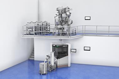
Croma continuous coater is designed to work in a truly continuous mode; the machine has a continuous feeding system upstream and a continuous discharging system downstream. The coater consists of an elongated perforated cylindrical drum, an inlet conveyor for the drying air and an outlet conveyor that forces the hot air to permeate the tablet bed. A modular coating arm with 10 nozzles ensures the tablets are coated as they transit the length of the drum.

Credit:
IMA Pharma[/caption]
CFD simulations were performed using STAR CCM+, Siemens software. A steady state analysis has been performed with compressible air and the flow has been modelled as turbulent with k-e model and Two-Layer all y+ wall treatment.
A total pressure boundary has been imposed on the inlet surface and a static pressure boundary has been imposed on the outlet surface to reach the target volume flow rate.
The tablet bed has been modelled as a porous region, and the porous coefficient comes from a calibration test done empirically on the coating machine. The CFD Domain has 46.9 million cells, the average mesh dimension is 10mm and is 0.5mm close to the conveyor distributor.
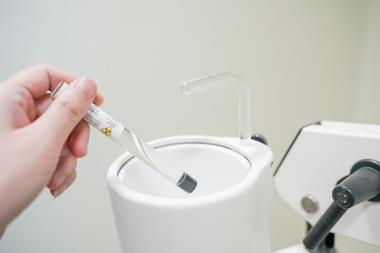
Trials have been performed in a Croma continuous coater, in an IMA Laboratory, to validate the CFD simulation model. Continuous coating processes have been performed to measure the temperature of the tablet bed at different points along the same using infrared sensors (pyrometers) and to evaluate the dirtiness of the coating arm after the trials.
Evaluation of the inlet conveyor flow performance
Efficacy with the continuous coater

Figure 2 (a) Conveyor with central inlet, (b) conveyor with lateral inlet
[/caption]
Previous studies on conveyors with two different air inlets (central and lateral) have shown that the central inlet of the conveyor does not give a uniform flow distribution since there is not enough space to let the air spread uniformly inside it. To reach uniformity, the distance of the inlet port from the drum had to be too great and the overall dimension of the coater had to increase. In order to have a compact and easy-to-use machine, it was decided to have a lateral inlet of the process air. So, the challenge was to find a compact conveyor with lateral air inlet which distributes the air equally through the length of the drum. (Figure 2)
Different conveyor configurations have been modelled with CFD, and two types of conveyor are investigated and compared in this article. The two conveyors have been tested at an air flowrate of 1000m3/h.
 Figure 3
 Boundary conditions
[/caption]
As mentioned above, the objective is to design a conveyor which equally distributes the airflow inside the coater. To achieve this goal, it is necessary to find a way to avoid all the air going on the front of the coater, and to distribute it also at the end of the coater.
STAR CCM+ is employed to study the uniformity of the air flow distribution in two different conveyors. Version 1 has a diffuser with holes at different diameters to convey air, whereas version 2 has a linear diffuser with openings of different widths. For both versions, flow distribution on the grid and on the tablet bed together with the velocity field have been evaluated by the model. Flow distribution has been evaluated by calculating a Uniformity Index.
Results and analyses
In Figure 4 it is possible to show the result of the air distribution on the grid of the two conveyors simulated on STAR CCM+
 Figure 4
. Air flow distribution in the Grid of the 2 conveyors
[/caption]
The Uniformity Index of Version 2 is higher, which means that the pressure drops of this type of diffuser spread the air more uniformly than the first one.
In Figure 5 it is possible to show the result of the air distribution on the tablet bed of the two conveyors simulated on STAR CCM+
Figure 5 shows that with version 2 there is a better distribution of the airflow on the tablet bed. Moreover, the velocities of the airflow are lower than Version 1, where an area of very high air velocity is visible near the front of the machine.
 Figure 5
. Air flow distribution on the tablet bed
[/caption]
Figure 6 shows the side view of the coater with the conveyor which guarantees the best air diffusion into the continuous coater.
 Figure 6
. Velocity Field of the version 2 conveyor in the side view of the coater
[/caption]
Trials have been conducted in Croma with both conveyors to evaluate the CFD model.
The same coating process has been carried out continuously for two hours. The dirtiness of the coating arm and the temperature on the tablet bed (measured in four different positions along the coater) have been evaluated to determine the best conveyor and to match the empirical results with the simulated ones.
The Pyrometers have been positioned at 200mm, 400mm, 600mm and 800mm from the front of the coater.
 Figure 7
. Coating arm at the end of a two-hour continuous coating process both for inlet air conveyor version 1 and inlet air conveyor version 2
[/caption]
Figure 7 shows the coating arm at the end of a two-hour coating process.
The table below shows the average temperature measured by pyrometers during the coating process.
| T1 (°C) | T2 (°C) | T3 (°C) | T4 (°C) | |
| Version 1 | 46.4 | 42.4 | 41.9 | 40 |
| Version 2 | 43.2 | 44 | 42.5 | 42.7 |
Table 1. Tablet bed temperatures at different positions on the tablet bed for the two different conveyors
Conclusion
Computational fluid dynamic analysis is performed on two different conveyor configurations to study air flow characteristics.
The results show that the conveyor with a linear diffuser (version 2) gives better air distribution than the version 1 conveyor. Effective simulation is also confirmed by empirical evidence.
Lower velocities and uniform distribution of inlet airflow leads to less spray losses, since the coating arm gets less dirty, and to a more uniform tablet bed temperature even with an elongated table bed.
Therefore, the application of modern computational simulation tools like CFD could be a valid way to overcome some of the limitations of experimental measurements. The computation simulation tools offer the opportunity to reduce the empirical trials, and hence costs, as well as to get a deeper understanding of the process.
References
- International Conference on Harmonisation of Technical Requirements for Registration of Pharmaceuticals for Human Use. Pharmaceutical Development Q8(R2). 2009.
- Turton, Richard; Challenges in the modeling and prediction of coating of pharmaceutical dosage forms, Powder Technology, 2008, 181, 186–194.